Metal shrinkage in castings and why it matters
Within this article, we take a look at one of the issues within metal casting that is critical to get right but challenging to understand, even for those within the industry. Shrinkage of metals as they cool is largely predictable under controlled conditions with external variables removed or clearly defined. Unfortunately, this is rarely the case when design and foundry engineers are confronted with a complex casting geometry and a plethora of variables that all have an influence on how a cast alloy will actually react, and in which directions contraction will occur.
Traditionally, the skill and experience of the patternmaker has been relied upon to arrive at a pattern that takes account of likely shrinkage and delivers a cast component that is within acceptable tolerances. As design technology and rapid prototyping techniques, such as 3D printing, have evolved, it is increasingly important that design engineers are aware of the complexities inherent in the metal cooling process. They are helped considerably by improvements in casting simulation software, that can be used to predict the way an alloy will react within a specified design, but managing molten metal is like handling a living thing, so an understanding of the external factors that may affect it is invaluable.
What kinds of shrinkage are there?
As molten metal cools, shrinkage occurs in three distinct stages:
- Liquid shrinkage is the contraction that occurs as the alloy cools but remains in its liquid state. This is not normally significant from a casting design perspective as more alloy can be drawn into the mould from the risers.
- Liquid-to-solid shrinkage (also known as solidification shrinkage) occurs as the alloy changes from a liquid to a solid. This is significant for the designer as it gives rise to the need to keep fluid metal channels open throughout the mould during cooling as contraction will draw more metal into the casting from the risers.
- Solid shrinkage is the continued shrinkage that occurs as the solid metal casting cools to ambient temperature in its solid state. This is also significant from the designer’s point of view. It is known as “Patternmaker’s Shrinkage” and must be compensated for within the tooling or mould design to ensure that the specified final overall dimensions are achieved.
The type of solidification that occurs is also important
Just as important from a casting geometry design perspective is the further classification of alloys by the type of solidification that occurs. There are three kinds as detailed below;
- Eutectic Solidification: These alloys remain in liquid form briefly in the mould but as soon as they start to cool solidification takes place rapidly throughout the casting. Internal shrinkage is minimal so risers are not so important as little additional alloy will be drawn into the mould. Examples or Eutectic alloys are Grey Iron, Aluminium 356, Silicon Bronze, Yellow Brass, Titanium and Zirconium.
- Directional Solidification: These alloys start to solidify quickly from the mould walls inwards. This makes them predictable and so good geometry design can take account of thermal gradient patterns to avoid closed pathways which could lead to internal shrinkage. Examples of Directional alloys are Carbon and Low Alloy Steel and Magnesium ZE43.
- Equiaxed Solidification: These alloys are somewhat unpredictable as they will start to solidify from the mould walls inwards but will also solidify in random internal islands which can block pathways. Fine, dispersed micro-porosity is typical of these alloys. Examples of Equiaxed alloys are Aluminium 356 and Aluminium Bronze.
How does this affect the manufacture of the pattern?
Whichever type of solidification occurs, Solid Shrinkage will result in an overall and relatively predictable contraction to the final size at ambient temperature. This must be allowed for in the construction of the patterns, dies or core boxes for mould making. It is important to note, however, that contraction may not be evenly distributed throughout the component. This can lead to the introduction of residual stresses and warping of the component unless the geometry design takes account of this risk.
Understanding the kinds of thermal patterns and solidification processes that will take place for each alloy is vital as it allows the designer to predict how solidification should occur. There are, however, additional complications even with the most predictable directional solidification. There will be differential cooling between cooler areas, where the mould surface area to metal volume is high, and other hotter areas, perhaps where metal volume is higher. Solidification will then travel inwards from the walls and from cooler to hotter areas. It is important, therefore, that the geometry allows for a clear liquid metal pathway to the hotter areas before solidification cuts them off from the riser. This is done through tapering and effective riser placement, without which, isolated internal shrinkage can occur giving rise to voids or pores.
How is this taken account of?
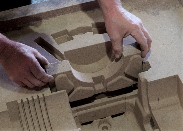
When producing a pattern, mould or core, patternmakers traditionally used scaled rulers called ‘shrink rules’ to account for the contraction of cast metals as they cool during the casting process. These allowed the dimensions of the pattern to be accurately adjusted to take account of the known shrinkage rates of different alloys. In modern foundries, these allowances are generally introduced to CAD files as scale factors during tool design.
Unfortunately, accounting for shrinkage in patternmaking can not be managed purely through scaling of CAD files. The geometry of the casting will also affect shrinkage allowances. Section thickness, section shape, ribs, bosses, cores and inserts will all influence shrinkage at specific points within the casting. It is fair to say that the more complex the geometry the less predictable the shrink rate will be.
In addition, the rigidity of the mould wall will play a role. For rigid moulds, such as airset sand moulds and permanent moulds, as used in die casting, shrinkage is regarded as linear and incorporates the dimensional shrinkage of the component once the alloy has solidified. This is not the case where the mould wall is weak, as in a green-sand mould, where wall movement during pouring and solidification will affect the shrinkage rate applied.
What allowances are made for different alloys?
One of the key determinants of the shrinkage allowance applied to patterns will be the alloy to be cast. Most molten metals will shrink as they solidify. For stainless steels and nickel alloys this might typically be 2-3% by volume, whereas for copper alloys it can be 5-6% and aluminium even more. It should be noted, however, that alloying elements will affect how much the resulting alloy will shrink during cooling. In some cases, as with cast aluminium alloys, their can be a considerable reduction in contraction so it is important to work with your foundry to determine the actual likely contraction rates for the specific alloy being cast.
Contraction rates vary widely between alloys but design engineers and patternmakers must also consider the overall size of the cast component alongside the alloy to be cast. As the allowance is linear, larger castings experience greater shrinkage as they cool and, as a result, a shrink allowance error is created that grows with the size of the casting. Consequently, graduated casting tolerances are used that grow as the casting increases in size, ISO 8062 covers this based on accepted processes and characteristics. Different tolerance grades are used for each casting process.
Clearly, pattern shrink plays an important part in determining the final dimensions of the casting and can influence subsequent machining and other downstream processes. Working closely with the foundry and their patternmakers is clearly vital to the successful delivery of a cast component.
Conclusion
It is essential to understand the contraction rates associated with ferrous and non-ferrous metals during the casting process. This article has provided an overview of the importance of understanding contraction rates, factors that affect them, and techniques for accurate control. Perhaps the key takeaway from this article is that partnering with an experienced casting supplier who understands these processes and how to control them, for the specific alloy you will be using, is essential to achieving successful results. By following best practices in accounting for contraction rates during casting operations, manufacturers can produce higher quality parts at lower costs while also reducing waste and improving efficiency.
NovaCast’s foundry has been enhanced by the addition of computer-based technologies, such as Casting Simulation and 3D Modelling software during recent years. Today, these technologies can shorten lead times from initial design submission to finished, cast component considerably but there is much that design engineers need to be aware of when considering the geometry of cast components.
Working closely with NovaCast’s Foundry Engineers or taking advantage of our in-house engineering design expertise can help to reduce lead times and cost, and ultimately improve the design of the cast component.
If you are investigating the best option for a cast or machined component and need to call on our experience and expertise we would be delighted to hear from you. Call a member of NovaCast’s team on +44 (0) 1225 707466, send us a message here or email sales@novacast.co.uk.